
Subject: 3G EWS remote fob programming
Background
I have a ’98 1.9 Z3 with the old style `house-brick’ remote and had problems with it not operating. I sought help on the zroadster forums and as is usual, there were lots of useful comments and links to previous threads on the subject. Many of these threads contain photographs from the experiences of other forum members.
Having rectified the initial problem (sticking buttons) using information provided, it was suggested that a write-up with photos, on the programming of the remote fob would be useful for the Knowledge Base. So here’s my effort including my own photos taken during the task.
Introduction
The system for my car is shown on:
http://bmwfans.info/parts/catalog/Z3/Roadster/Europe/Z3_1.9-M44/RHD/N/1997/december/browse/vehicle_electrical_system/remote_control_version_1/
In order to program new remote fob or re-program an old one, you have to access the EWS Control box and move a selector switch to the `learn’ position. The EWS control box is situated behind the glove box so it is necessary to remove this to gain access.
I bought a new OEM `house-brick’ (82 92 9 404 882) and programmed this and also my old rather `tired’ unit which had given me the initial problem.
If you are re-programming an old unit, I would advise you give the buttons a good clean first (switch solvent /cleaner) and fit a new 23A 12v battery (cost ~£3).
You will need to buy a battery for a new OEM unit as they are not included, despite paying just over £53, with the unit.
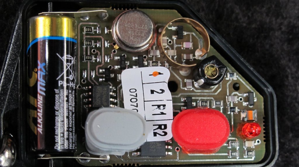
Note: +/- terminal idents are marked in the bottom of the fob case.
Once fitted press `on’ and `off’ buttons and check red transmit LED on the remote(s) illuminates.
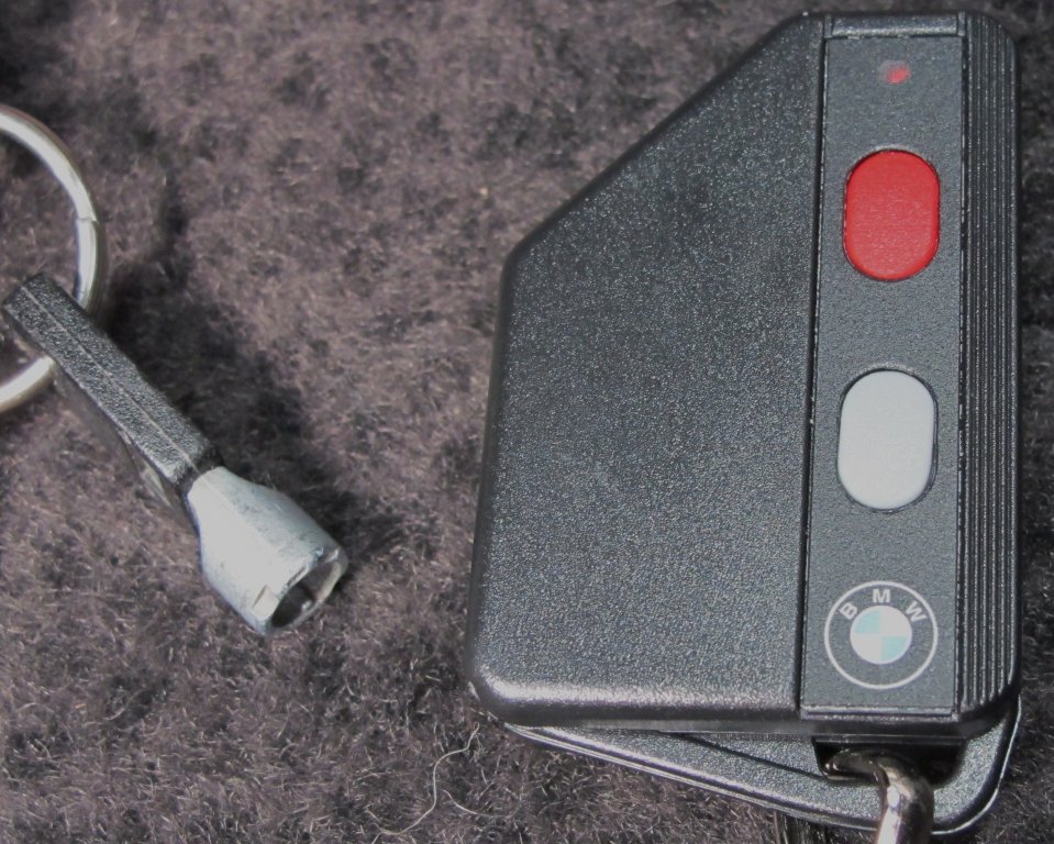
These next 2 photos show new remote and internal view. (For information – they key on the left is for the audible alarm under the bonnet).
Stage 1. – Glove Box removal
On my car there are 6 Philips screws holding the box and surround panel in position and you will need to prise the rubber covering caps off to access these. The screws are situated as follows:
No.1- Top left corner – accessed from door jamb - short handled driver or ratchet required, Nos. 2&3 are inside box either side of lock, No4 is in the top right corner and Nos 5&6 at lower right where glove box panel is joined to centre console.
Note: for re-assembly screws 1 and 4 are longer than the other four.
In addition, there is an in-fill panel on the lower edge of the box. To remove this panel, firstly undo and remove the two plastic `push and turn’ plugs, then unclip the panel.
Once all disconnected, gently pull the top left hand side of the box panel forward and then un-hook the right hand lower corner from behind the centre console panel.
Stage 2 – accessing selector switch
TIP: Put some padding over the door sill – my ribs were still sore 2 days later!
Make sure ignition is off – remove keys.
With the glove box now removed you should have this view.
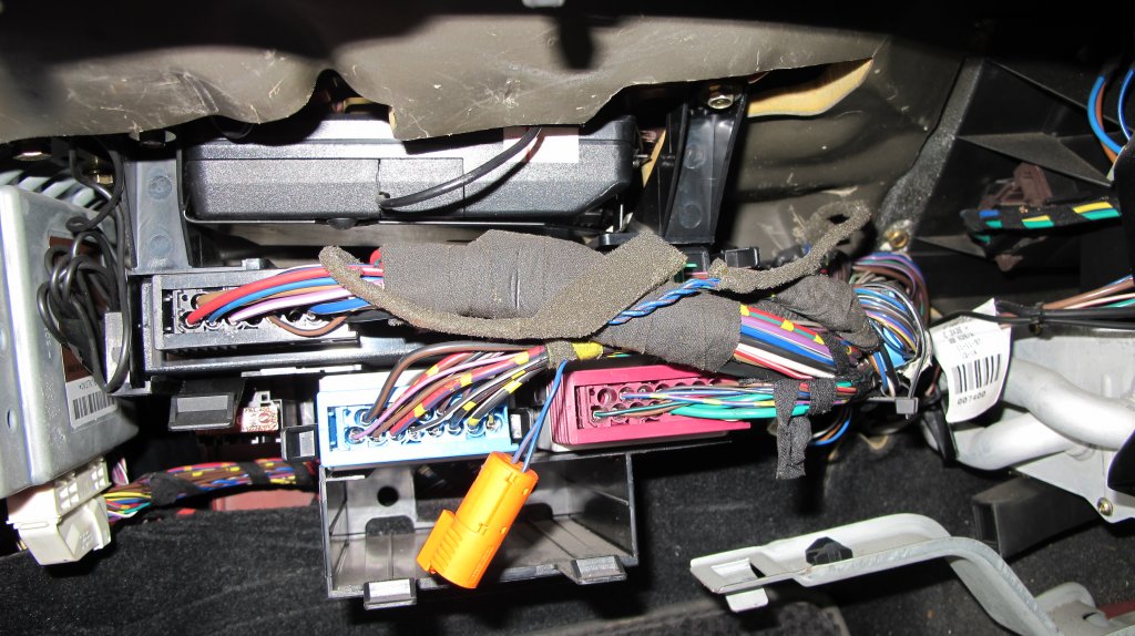
The control unit is the black box at the top of screen. (For information only - the silver box to the left is the ABS/ASC control unit).
The black co-axial cable exiting the centre of the box is the aerial cable. This loops behind box (surplus coils can be seen tucked in at the left side of the box) and then leads up the passenger side door pillar.
The rubber bung in the centre of the box is sealing the access point to the program selector switch.
Some members have said they managed to operate the programming switch at this stage by using a long screw driver and angled mirror. I could not, so I proceeded to drop wiring loom and remove control box.
The wiring loom is supported on a plastic hanger bracket which is bolted to the bulk head either side of the control box. Loosen these bolts, I used a VBA2 socket, and slide the brackets backwards and then down.

The EWS control unit sits in a metal cradle which is screwed to the bulk head. The screws are Torx with centre security pin – I replaced them with Philips on re-assembly.
Once the cradle is dropped then you can examine the control box.
This is the top side with rear connections:

This is the bottom view with the rubber bung removed – is there really a switch here you may ask – I certainly doubted it.

Bottom view - Hidden' switch to right of hole.
I had been told it was “offset” but could not see anything, so I dug in with a small screw driver and managed to move something over and found this:

Switch in `learn' position
Stage 3 - Programming
With the switch in this `learn’ position press the red button on your remote. The central locking and alarm system should activate. Press the grey button and the system should de-activate.
Repeat this operation for additional remote fobs – other threads say up to 4 can be programmed but I only had 2.
Once complete move the slider/switch back to `hidden’ position and check remote operation again. Mine did not work at first attempt, so I pushed the slider switch a little further over and then all was ok.
Stage 4 – Re-assembly
Re-trace previous steps. I would suggest you check remote operation at each stage just in case you disturb any wiring.
Background
I have a ’98 1.9 Z3 with the old style `house-brick’ remote and had problems with it not operating. I sought help on the zroadster forums and as is usual, there were lots of useful comments and links to previous threads on the subject. Many of these threads contain photographs from the experiences of other forum members.
Having rectified the initial problem (sticking buttons) using information provided, it was suggested that a write-up with photos, on the programming of the remote fob would be useful for the Knowledge Base. So here’s my effort including my own photos taken during the task.
Introduction
The system for my car is shown on:
http://bmwfans.info/parts/catalog/Z3/Roadster/Europe/Z3_1.9-M44/RHD/N/1997/december/browse/vehicle_electrical_system/remote_control_version_1/
In order to program new remote fob or re-program an old one, you have to access the EWS Control box and move a selector switch to the `learn’ position. The EWS control box is situated behind the glove box so it is necessary to remove this to gain access.
I bought a new OEM `house-brick’ (82 92 9 404 882) and programmed this and also my old rather `tired’ unit which had given me the initial problem.
If you are re-programming an old unit, I would advise you give the buttons a good clean first (switch solvent /cleaner) and fit a new 23A 12v battery (cost ~£3).
You will need to buy a battery for a new OEM unit as they are not included, despite paying just over £53, with the unit.
Note: +/- terminal idents are marked in the bottom of the fob case.
Once fitted press `on’ and `off’ buttons and check red transmit LED on the remote(s) illuminates.
These next 2 photos show new remote and internal view. (For information – they key on the left is for the audible alarm under the bonnet).
Stage 1. – Glove Box removal
On my car there are 6 Philips screws holding the box and surround panel in position and you will need to prise the rubber covering caps off to access these. The screws are situated as follows:
No.1- Top left corner – accessed from door jamb - short handled driver or ratchet required, Nos. 2&3 are inside box either side of lock, No4 is in the top right corner and Nos 5&6 at lower right where glove box panel is joined to centre console.
Note: for re-assembly screws 1 and 4 are longer than the other four.
In addition, there is an in-fill panel on the lower edge of the box. To remove this panel, firstly undo and remove the two plastic `push and turn’ plugs, then unclip the panel.
Once all disconnected, gently pull the top left hand side of the box panel forward and then un-hook the right hand lower corner from behind the centre console panel.
Stage 2 – accessing selector switch
TIP: Put some padding over the door sill – my ribs were still sore 2 days later!
Make sure ignition is off – remove keys.
With the glove box now removed you should have this view.
The control unit is the black box at the top of screen. (For information only - the silver box to the left is the ABS/ASC control unit).
The black co-axial cable exiting the centre of the box is the aerial cable. This loops behind box (surplus coils can be seen tucked in at the left side of the box) and then leads up the passenger side door pillar.
The rubber bung in the centre of the box is sealing the access point to the program selector switch.
Some members have said they managed to operate the programming switch at this stage by using a long screw driver and angled mirror. I could not, so I proceeded to drop wiring loom and remove control box.
The wiring loom is supported on a plastic hanger bracket which is bolted to the bulk head either side of the control box. Loosen these bolts, I used a VBA2 socket, and slide the brackets backwards and then down.
The EWS control unit sits in a metal cradle which is screwed to the bulk head. The screws are Torx with centre security pin – I replaced them with Philips on re-assembly.
Once the cradle is dropped then you can examine the control box.
This is the top side with rear connections:
This is the bottom view with the rubber bung removed – is there really a switch here you may ask – I certainly doubted it.
Bottom view - Hidden' switch to right of hole.
I had been told it was “offset” but could not see anything, so I dug in with a small screw driver and managed to move something over and found this:
Switch in `learn' position
Stage 3 - Programming
With the switch in this `learn’ position press the red button on your remote. The central locking and alarm system should activate. Press the grey button and the system should de-activate.
Repeat this operation for additional remote fobs – other threads say up to 4 can be programmed but I only had 2.
Once complete move the slider/switch back to `hidden’ position and check remote operation again. Mine did not work at first attempt, so I pushed the slider switch a little further over and then all was ok.
Stage 4 – Re-assembly
Re-trace previous steps. I would suggest you check remote operation at each stage just in case you disturb any wiring.
