Z3(00S) - EV project

Tom Cheesewright

Zorg Guru (I)
Supporter
British Zeds
Joined
May 6, 2020
Points
90
Location
Manchester, UK
Model of Z
Z3
Following on from my intro (https://zroadster.org/threads/trigger-warning-ev-and-body-conversion.37361/) someone (thanks Stephen) suggested I post a progress thread here about my EV conversion and eventually, body conversion of a Z3.

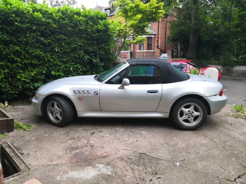
So, brief recap: my daughter and I have bought a high mileage '99 1.9 Z3 with the aim of first converting it to electric power, and ultimately (when time and funds allow) doing the Tribute Automotive Z300S body conversion. We've been playing with components for the last few weeks and finally found a donor car, albeit at the other end of the country. It will be heading up to us in Manchester in a couple of weeks.

I'm maintaining a sort of build blog (more documenting what we've done for our own sakes) over at http://projects.tomcheesewright.com/ev-project.html but I'll cross post some stuff here as well.

The plan is to remove the M44 lump (soon for sale - along with most of the ancillaries) and replace it with one of the motors from the Mitsubishi Outlander PHEV. There are more powerful options available that we might explore down the line but this is a fairly cheap way to go for now and should give us roughly equivalent performance to the old 1.9 unit if my bad maths are right (and if we can make it work).

Power will come initially from the battery from a modern BMW 330e hybrid, fed via a modified Prius inverter that is currently in pieces on my bench. A new control board is on its way from EVBMW. Down the line we might add more batteries for increased range in the spaces vacated by the fuel tank (also soon for sale).

All of this is still a little bit provisional. I have a mostly-forgotten engineering degree, some experience playing with cars, and some basic skills but we're on a steep learning curve. Don't be surprised if all the above changes in five posts' time!

I'm currently working up an adapter plate and a donut to bolt on the original flywheel in CAD. If anyone can recommend people to make up adapters then that would be very welcome - otherwise we will be either looking for a local engineering company or one of the online prototype machining places.

Picture below shows me test-fitting a 3D-printed template to the motor for some of the holes that will need to go in the adapter plate - holes that are clearly in the wrong place thanks to my poor measuring.

More to come...
IMG_20200517_201602.jpg
 

Stevo7682

Zorg Expert (I)
Supporter
The M44 Massive
Scottish Zeds
Joined
Apr 1, 2016
Points
208
Location
Maybole , South Ayrshire
Model of Z
Z3 Individual Dakar / Orinoco Individual
I'm going to throw a minor problem your way in regards to the fuel tank .
I am relatively sure you can't take the tank out a zed 3 without removing the rear axle assembly
20200517_213335.jpg
 

pgunter

Zorg Guru (V)
Supporter
British Zeds
#ZedShed
Joined
Aug 15, 2014
Points
185
Location
Winchester
Model of Z
2.2i Sport Zedshed Special
I will watch this with interest.

as mentioned above, the rear beam has to be dropped to get the fuel tank out.

good luck with the build.
 

Althulas

Zorg Guru (V)
Supporter
British Zeds
Joined
Jun 14, 2014
Points
178
Location
Banburyshire
Model of Z
M Roadster
The rear beam bushes will most likely be knackered anyway so a good chance to replace and clean up the rear end anyway. If your conversion is going to add a lot more torque you might want to check the condition of the spot welds around the diff hanger and boot area as these are prone to popping on more powerful versions and You might want to consider some strengthening.
 

Tom Cheesewright

Zorg Guru (I)
Supporter
British Zeds
Joined
May 6, 2020
Points
90
Location
Manchester, UK
Model of Z
Z3
I'm going to throw a minor problem your way in regards to the fuel tank .
I am relatively sure you can't take the tank out a zed 3 without removing the rear axle assembly View attachment 142633
You say problem, I say "learning opportunity"... ;)

I was kind of expecting something like that TBH. I have ramps and axle stands. Sounds like there's a regular problem with the rear diff mount as well? May be an opportunity to do it all at the same time and maybe refurbish that whole assembly.
 

Tom Cheesewright

Zorg Guru (I)
Supporter
British Zeds
Joined
May 6, 2020
Points
90
Location
Manchester, UK
Model of Z
Z3
The rear beam bushes will most likely be knackered anyway so a good chance to replace and clean up the rear end anyway. If your conversion is going to add a lot more torque you might want to check the condition of the spot welds around the diff hanger and boot area as these are prone to popping on more powerful versions and You might want to consider some strengthening.
Thanks for that. Current version won't be that powerful but if I'm planning to upgrade to the Lexus drive system (300hp) down the line then it might be worth doing some pre-emptive strengthening now. Can put my daughter's newly-acquired welding skills to the test!
 

Tom Cheesewright

Zorg Guru (I)
Supporter
British Zeds
Joined
May 6, 2020
Points
90
Location
Manchester, UK
Model of Z
Z3
Bit of a motor update. I couldn't find any diagrams of the mounting points for the PHEV front motor. At least, not ones with measurements. So I set about making a simple CAD model of the motor face in order to map out the bolt pattern.

Without a 3D scanner (a hole in my toolkit I would very much like to fill), my best option (other than maybe a paper template) seemed to be to try to measure the rather uneven surface with calipers and a ruler and transfer those measurements into Fusion. I then 3D printed a simple template with a hole for the single dowel and plugs for the two M8 threaded holes and four 11mm holes. After about ten iterations of the 3D printed model (see picture), I finally had a model that fitted accurately - at least to within a few fractions of a millimetre (note - this is not the one in the picture below).

I have a little more testing to do but then I'm happy share my template with others looking to use this motor. When the car arrives and we have removed the gearbox, I will map the motor mounting holes against the ones on the gearbox and design up a full adaptor plate. Then I can sort out the adaptor between the splined shaft and the BMW flywheel. Looking at places to get that machined at the moment.

outlander-phev-motor-mounting-template_small.jpg
 

Tom Cheesewright

Zorg Guru (I)
Supporter
British Zeds
Joined
May 6, 2020
Points
90
Location
Manchester, UK
Model of Z
Z3
Finished soldering up test cables for the motor and throttle last night. Probably not necessary for testing, but using some of the shielded twisted pair I bought to use in the car where there will be lots of EMF noise. Replicating some of the stuff from the blog for posterity here.

##

I'm planning to use a BMW 1-Series Throttle Pedal, though I think they are fairly similar across a number of cars. This cost me £10.49 inc shipping from eBay, which seemed very reasonable. My unit came in good condition with the connector plug attached and some decent length tails on it.

I found the pin out information on a forum post on a racing simulator site of all places:

Pin 1: GND 1 - Brown/Yellow (apparently brown and green on the E46 pedal)
Pin 2: GND 2 - Brown
Pin 3: VCC 2 - Yellow/Green
Pin 4: SIG 1 - White
Pin 5: VCC 1 - Yellow
Pin 6: SIG 2 - White (apparently white/green on the E46)

From this I could tell that the pedal probably has two position sensors that each take an input voltage and return a signal. But I wasn't sure if it was resistive or encoder-based at first. A bit of googling told me the electronics expect 5V on a modern BMW so I hooked the pedal up to the bench power supply and a multimeter and took some voltage readings (i.e. 5V to VCC 1, Ground and multimeter ground to GND 1, and multimeter to SIG 1, then repeat for SIG 2). My bench power supply is actually an old PC PSU (I do love to recycle) so it isn't adjustable and doesn't give me exactly 5V. Measured at 5.13V while testing.

Here are the results:

SIG 1
Throttle at rest: 0.73V
Throttle at full travel: 4.00V

SIG 2
Throttle at rest: 0.36V
Throttle at full travel: 2.02V

So, the output of SIG 1 has exactly twice the resolution of SIG 2. Guess there are two for safety reasons? [this website confirms that]. Either way I now know how to get the output of my throttle and feed it to the inverter control board.

Note on the connector: It's a Tyco unit (expensive) but there are nice cheap clones available on AliExpress - search for 967616.

bmw-throttle-pedal.jpg
bmw-throttle-pedal-connector.jpg
bmw-throttle-pedal-connector-2.jpg
 

Tom Cheesewright

Zorg Guru (I)
Supporter
British Zeds
Joined
May 6, 2020
Points
90
Location
Manchester, UK
Model of Z
Z3
Right, time for an update. The car has arrived! Rolled off the transporter this morning. And after waiting for some joker to unblock my driveway, I got it home.

Car runs nicely with a bit of right boot but won't idle and there's an engine management light on. Not got the diagnostics hooked up yet so not sure what the cause is, but if anyone's in the market for a four pot with 'only' 174,000 miles on it, then let me know!

First inspection only threw up a few things that need doing... Most of them are straightforward - door dings, broken aerial, rust on slam panel. Fair few scrapes, dings and cosmetic rust, but since I'll be doing a body swap that doesn't worry me (doors matter as those are kept with the body swap. Important stuff: no signs of structural rust yet (until I get those sills off) and it is very clean in the boot and under the bonnet. Hood seems in good nick with the rear window only slightly milky. Good for a few years yet, even in Manchester weather.

Things that do need doing:

- Electric hood doesn't work (more on this to come)
- Driver's side wing mirror needs replacing (currently held together with duct tape)
- Both sills are badly rusted at the ends (these will be replaced as they are kept on the Z300)
- Boot gas struts have failed (new ones ordered)
- Passenger door central locking doesn't work - boot and drivers door fine
- Driver's side electric seat tilt doesn't work (moves back and forward fine)
- Water ingress in boot (carpets damp and a puddle in the left hand well below the hood hydraulics)

Took some measurements under the bonnet and the battery pack I want to use *should* fit length and width-wise, with some alterations to the radiator shroud and fan - though I'll likely swap these out for a smaller unit that can be mounted further forward and sell them on.

Still need to have a look through the service history. Then the plan is to get it up on ramps & stands and have a look underneath before we start stripping it. Oh, and I need to tap into the CANBus and capture all the messages I'll later have to spoof before I start taking the engine out. Mustn't forget to do that...
 

Attachments

Tom Cheesewright

Zorg Guru (I)
Supporter
British Zeds
Joined
May 6, 2020
Points
90
Location
Manchester, UK
Model of Z
Z3
So, the electric hood. Yet to do a really deep dive on all the relevant threads here but here's what we have so far:

- Checked the fuse - that's fine
- Initially when we un-clipped the top and put a foot on the brake, there was a clicking from the back when the switch was pressed
- The battery then went flat (not sure of any connection - could be just all the testing of windows/seats etc)
- Hooked up a second battery and couldn't get it to click again
- Peeled off the carpet around the hydraulics and found that the rubber bush had been replaced with medical gloves???!!?! (wish I had taken a photo before I removed it but I was in shock)
- The bottom bolt where the earth connection is was also very loose.
- Found the bush - they'd left it in the bracket - unbolted it all, refitted and tightened everything up
- Still no joy
- Fuse still good.

Going to slacken off the T-bar on the pump for now and use it manually but need to do more investigating. Need to check boot loom, microswitches, and relays from what I've read so far.
 

Attachments

t-tony

Zorg Expert (II)
Supporter
British Zeds
#ZedShed
Joined
Dec 31, 2013
Points
226
Location
Torksey Lock,Lincoln, England
Model of Z
E89 Z4 23i Auto
Hi Tom, when I had my Z3I had issues with N\S door C/locking (everything else was fine) and it turned out to be the locking solenoid in the N\S door. I got a non genuine aftermarket replacement for (as best I can remember) around £35.

Tony.

ps. One of our resident breakers may be able to help you with one. @spurs fan in a coupe , @Synclare or perhaps Rob at @mrscalex who does sometimes have parts he doesn't need.
 

Tom Cheesewright

Zorg Guru (I)
Supporter
British Zeds
Joined
May 6, 2020
Points
90
Location
Manchester, UK
Model of Z
Z3
Thanks @t-tony - that's definitely my first port of call as all the other parts of the locking system seem to be fine. Might get the door card off this weekend to take a look.

Thanks @Althulas - I've printed out the wiring diagram from the fault-finding manual somewhere here and will be going through and tracing it to see what I can find.
 

Davyhoogy

Zorg Guru (III)
Joined
May 4, 2016
Points
148
Location
Sunderland
Model of Z
'98 2.8 z3
If I haven’t missed it anywhere, a quick fix when my roof stopped working was the micro switch. Just above the passenger window, cut the wires and join them. Although it doesn’t sound like this was the issue if you heard clicking from the rear when pressed.

Very interesting project! Very good luck to you.
 

Tom Cheesewright

Zorg Guru (I)
Supporter
British Zeds
Joined
May 6, 2020
Points
90
Location
Manchester, UK
Model of Z
Z3
Roof FIXED! Turns out that the problem was the dodgy earth on the hydraulic pump and we just had the key in the wrong position when I did the second set of tests. Now goes down (with a little help at first) and back up very smoothly. Kids are hugely excited by this development.

On to the central locking. Door card is off and I'll try to remove the actuator for a look at that tomorrow.
 

Tom Cheesewright

Zorg Guru (I)
Supporter
British Zeds
Joined
May 6, 2020
Points
90
Location
Manchester, UK
Model of Z
Z3
Right, update time. Has been a busy couple of weeks work-wise but still managed to make some progress. And I'm taking the rest of this week off to work on the car.

Have fixed the main issues with the car itself. Like the power hood, central locking just seemed to be bad earth/connection issue. Once I stripped off the actuator, greased it and put it back together, it worked fine. Picked up a second hand driver's door mirror from this forum and fitted that. Not as cheap a job as I was hoping but easy at least.

Got diagnostics onto the engine and it confirmed what the high-pitched whistle told me: vacuum leak was the reason for the warning light on the dash. Plus the secondary air pump is knackered and detached from its mountings. And there's a split in the air intake hose that connects to the MAF. All standard stuff and not really worth fixing before I pull the lump out. Engine is high mileage but runs very nicely with a little throttle. If anyone needs any parts from a 99 Z3 1.9 then let me know.

Have been trying to get my head around the car's use of CAN and I can't really find that I'm going to need to worry much about it. Only concerns are with engaging the active stability control and the ABS, but I can't see that either actually need CAN messages to engage. And neither appear to use CAN to communicate with the dash. In fact the dash seems to be largely old-school with lots of mostly 12v signals for various faults. If anyone knows different I would love to hear but at the moment the plan is to pull the engine next week when the driveway is clear (builders in this week).

In the meantime we're cracking on with the drive unit. The inverter is back from my electronics saviour after I completely failed at soldering up the new control board. I've tested it and it seems to be working fine.

A test board with all the high voltage components (contactors, pre-charge relay etc) and the control elements (throttle, keyswitch, button to represent brakes) is mostly wired up - should get that finished today assuming some more nuts turn up for the HV connections (though it's only getting ~28V at the moment). And then be able to start testing the electric motor. Photo below if you're interested - the washing machine heating element is being used as a current limiting resistor for testing btw and won't be part of the final thing!

Lots of 3D printed parts required for this project. I'm designing replacement blanking plugs and connector housings for all the ports on the inverter that either now aren't used or are taking different cables to before. Happy to share if anyone else goes down this crazy route.

If all goes to plan we should be pulling the engine and gearbox out next week, and assuming we have the motor spinning by then it will be on to designing and fabricating adapters. Already have rough designs in Fusion360. I will 3D print the spline adapter before sending the design off for milling. Hoping that a little heat on the final version will give me the leeway I need to overcome any inaccuracies in my measurements and 3D printed model.

Fingers crossed..

IMG_20200616_080119.jpg
 

Tom Cheesewright

Zorg Guru (I)
Supporter
British Zeds
Joined
May 6, 2020
Points
90
Location
Manchester, UK
Model of Z
Z3
Bad news: the inverter still doesn't work properly. Looks like my saviour didn't quite solder up the very challenging 50 pin connector on the controller board correctly. This led to some very weird results, including the inverter repeatedly tripping out for excess voltage. I was feeding in about 24 volts, it was reading 800. Annoying.

So, I've contacted a couple of local electronics repair places with specialisms in fine SMD soldering. Hoping they can get me up and running this week.

In the meantime, I have all the HV circuit running beautifully. Before the DC measurement started floating, I could turn the keyswitch and the pre-charge relay would take the capacitors in the inverter up to voltage. Then when I turned to the start position, the main contactor would drop in, giving it the full juice.

Forward and reverse, throttle and brake sensors all also working on the test rig. So when the control board comes back from repair, I should be straight into testing. Pic below is a bit of a mess, partly because it's taken after I tore down the inverter again in frustration. But it all works.

IMG_20200620_085724.jpg

##

With scaffolding taking up most of the drive and none of the electronics engineers I've contacted about fixing my inverter not available over the weekend, there was only one job I could tackle: fixing the driver's seat tilt.

This clicked when the switch was pushed and even shuddered slightly, but didn't move. I popped the hood down and unbolted the seat per the instructions on here, then flipped the seat over. It was precisely as disgusting as you would expect for a 21yo car.

Once I worked out how the mechanism worked, I popped the pivot pin out of the end of the retainer into which the threaded rod slides for the tilt mechanism. But even when I lifted the forks away from the frame it wouldn't turn by hand. I stuck an adjustable spanner around it and gave it a gentle twist and slowly it started to come around.

What I found in the (open) other side was that a penny had fallen in and become wedged under the end of the screw. This was in turn gummed in with what looked like some melted sweets.

A bit of cleaning and levering later and one very deformed penny came out. I put it all back together with some fresh grease and sure enough, the tilt now works fine.

Pic below is after I had scraped a lot of the gunk away...

seat-tilt-ballscrew.jpg
 
Top