Hello!
I am finally ready to install the new intake manifold on my recently acquired 120K mile 1999 Z3 2.3 after a cooling system overhaul. Since the manifold needed to be removed in order to replace the plastic cooling pipes, I opted to upgrade to the M54B25 intake manifold for better breathing.
What follows is my attempt to unravel the correct routing and connections for the manifold. I did not do the detailed job I should have when I removed it while following the Bentley manual. I should have labeled every connection with a beginning and end so that I could reinstall the manifold properly. After much reading and forum/YouTube/realoem searching I think (I hope) I have most of it correct.
There are somewhere around 40 connections. I took masking tape and Sharpie in hand and began labeling each connection with a number using the same number for both ends. Some were really obvious. Some were easy due to the length of a plug and the proximity of the socket. Some were far less obvious and still one is unconfirmed. I am still new to this car. When it comes to vacuum lines, their purpose, function, etc. I am well out of my league.
For the electrical connections, I have been informed that each plug/socket combination is different, eliminating the possibility of inserting the wrong plug into a given socket. Very cool!
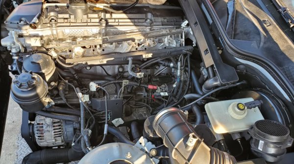
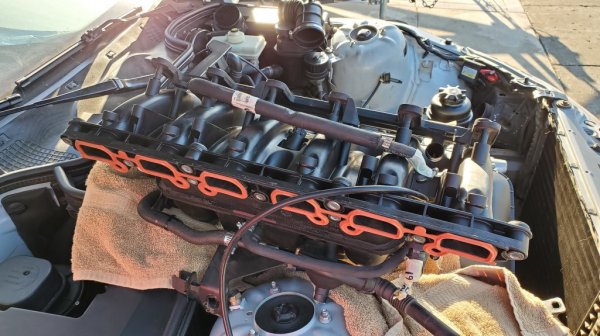
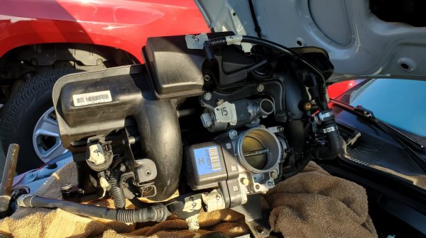
As for the images below, they were taken with the intake manifold sitting on top of the right strut tower generally in the correct orientation. The fuel rail and injector plug rail are well out of place. There are a couple of overview pictures including one of the open engine bay under the manifold location. Following are the first 18 connections. ZRoadster.org allows a maximum of 20 images per post so I am placing the remaining connections on a second thread that can be seen at: Vacuum and Electrical M54B25 on M52TU - Part 2
Any comments, corrections or questions, please let me know on this forum. Thank you!
Overview Images:
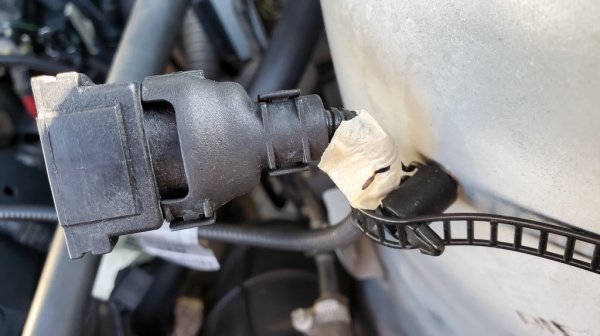
Connection #1
Portion of air inlet to plug on driver's side strut tower:
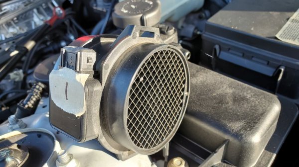
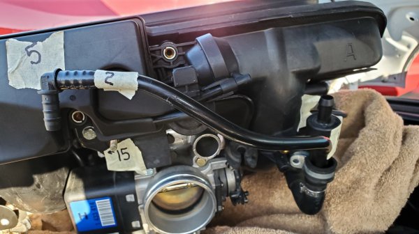
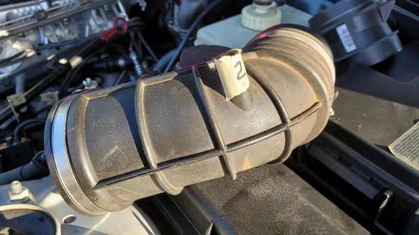
Connection #2
Medium hard plastic vacuum hose from right side of manifold to portion of air inlet pipe:
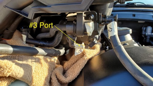
Connection #3
Vacuum hose from next to driver's side strut tower to valve on front of manifold:
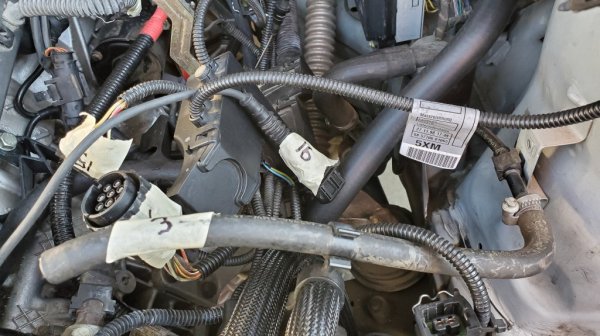
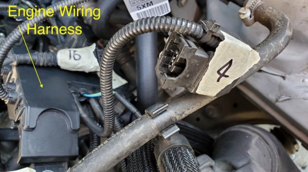
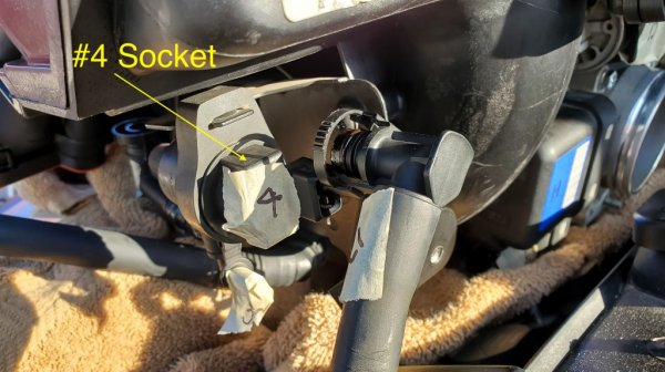
Connection #4
Plug from Engine Wiring harness to valve on front of manifold:
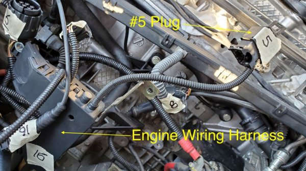
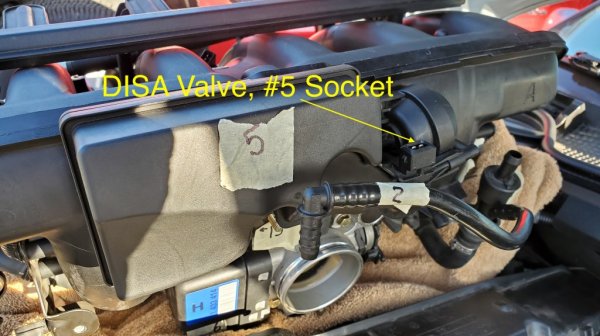
Connection #5
Plug from Engine Wiring Harness to socket on DISA valve:
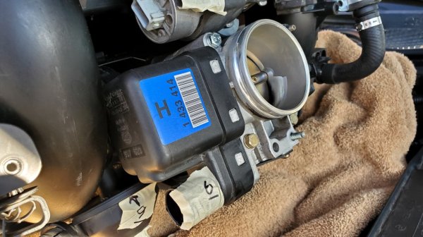
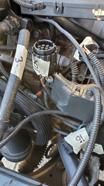
Connection #6
Round multi-pin plug from Engine Wiring Harness to lower left side of throttle body:
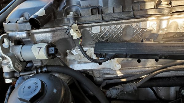
Connection #7
Plug from fuel injection power rail to socket near VANOS valve:
Connection #8
Plug from fuel injection power rail to socket on manifold between cylinders 3 and 4:
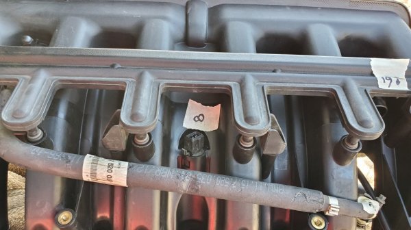
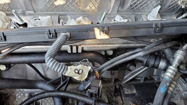
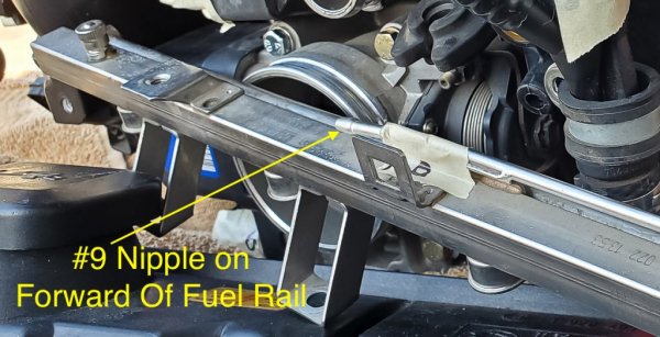
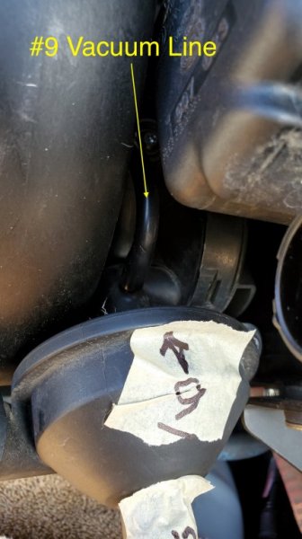
Connection #9
Vacuum line from metal nipple toward front top of fuel rail to pressure regulating valve (CCV):
See Part 2 at: Vacuum and Electrical M54B25 on M52TU - Part 2
I am finally ready to install the new intake manifold on my recently acquired 120K mile 1999 Z3 2.3 after a cooling system overhaul. Since the manifold needed to be removed in order to replace the plastic cooling pipes, I opted to upgrade to the M54B25 intake manifold for better breathing.
What follows is my attempt to unravel the correct routing and connections for the manifold. I did not do the detailed job I should have when I removed it while following the Bentley manual. I should have labeled every connection with a beginning and end so that I could reinstall the manifold properly. After much reading and forum/YouTube/realoem searching I think (I hope) I have most of it correct.
There are somewhere around 40 connections. I took masking tape and Sharpie in hand and began labeling each connection with a number using the same number for both ends. Some were really obvious. Some were easy due to the length of a plug and the proximity of the socket. Some were far less obvious and still one is unconfirmed. I am still new to this car. When it comes to vacuum lines, their purpose, function, etc. I am well out of my league.
For the electrical connections, I have been informed that each plug/socket combination is different, eliminating the possibility of inserting the wrong plug into a given socket. Very cool!
As for the images below, they were taken with the intake manifold sitting on top of the right strut tower generally in the correct orientation. The fuel rail and injector plug rail are well out of place. There are a couple of overview pictures including one of the open engine bay under the manifold location. Following are the first 18 connections. ZRoadster.org allows a maximum of 20 images per post so I am placing the remaining connections on a second thread that can be seen at: Vacuum and Electrical M54B25 on M52TU - Part 2
Any comments, corrections or questions, please let me know on this forum. Thank you!
Overview Images:


Connection #1
Portion of air inlet to plug on driver's side strut tower:


Connection #2
Medium hard plastic vacuum hose from right side of manifold to portion of air inlet pipe:


Connection #3
Vacuum hose from next to driver's side strut tower to valve on front of manifold:


Connection #4
Plug from Engine Wiring harness to valve on front of manifold:


Connection #5
Plug from Engine Wiring Harness to socket on DISA valve:


Connection #6
Round multi-pin plug from Engine Wiring Harness to lower left side of throttle body:


Connection #7
Plug from fuel injection power rail to socket near VANOS valve:

Connection #8
Plug from fuel injection power rail to socket on manifold between cylinders 3 and 4:


Connection #9
Vacuum line from metal nipple toward front top of fuel rail to pressure regulating valve (CCV):


See Part 2 at: Vacuum and Electrical M54B25 on M52TU - Part 2
Last edited:
